


Optical micromanipulation—including techniques that use light to trap and manipulate microscopic objects—was revolutionized by Arthur Ashkin’s invention of the optical tweezer in the 1980s. Optical tweezers rely on gradient and scattering forces from a tightly focused laser beam to control micro‑objects; while highly effective in controlled settings, they face limitations when handling targets of varying size, shape, or refractive index, and their high‑intensity beams can damage sensitive biological samples (e.g., cells).
By contrast, optoelectronic tweezers (OET) can manipulate multiple targets in parallel and use low‑intensity light sources to minimize photodamage. Although prior studies have explored the effects of AC voltage and light intensity on OET performance, little attention has been paid to how the curvature of the light pattern itself influences OET manipulation.
This work focuses on how light‑pattern curvature affects the motion of polystyrene (PS) microparticles under negative dielectrophoretic (DEP) forces in an OET system, and demonstrates that by optimizing light‑pattern design one can significantly improve manipulation speed and precision.
I. Research Team
Led by Prof. Shuailong Zhang of Beijing Institute of Technology and Prof. Na Liu of Shanghai University in collaboration with OptoSeeker, this study leverages the OptoBot®500 Optoelectronic Tweezer System to probe new possibilities in OET‑based micromanipulation. Their joint paper,
“Optimizing light pattern curvature to improve the performance of optoelectronic tweezers in micromanipulation,”
was recently published in Optics Express.
II. About Optics Express
Optics Express, launched in 1997 by the Optica Publishing Group, is a fully electronic, open‑access, semimonthly journal and a top‑tier (Q2) publication in the Chinese Academy of Sciences’ optics category. In 2024 it held an impact factor of 3.2.
III. Key Findings
-
High‑Precision Assembly & Parallel Control
The OptoBot®500 system enabled precise alignment and assembly of nanoparticles, as well as simultaneous control of multiple targets. -
Curvature Matters
By systematically varying the inner diameter of semi‑circular light patterns, the team demonstrated that curvature dramatically influences DEP forces, equilibrium positions, and maximum transport velocities. -
Optimal χ Ratio
They identified an optimal ratio χ—defined as the light‑pattern inner diameter divided by particle diameter—at χ = 5, which yields maximal horizontal and vertical DEP forces, highest transport speed, and greatest stability.
These results provide critical theoretical guidance for enhancing OET performance in applications spanning cell manipulation, biomedical diagnostics, materials science, nanofabrication, and other interdisciplinary fields.
IV. Experimental Approach
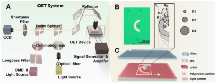
Figure 1. Schematic of the OET System.
(A) Overall layout of the optoelectronic tweezer (OET) setup.
(B) Experimental image and schematic of polystyrene (PS) microparticles manipulated by a semi‑circular light pattern.
(C) Structure of the OET chip.
To investigate how light‑pattern curvature influences particle motion, the team designed semi‑circular illumination patterns to actuate spherical PS microparticles. This simplified model highlights the interplay between microscale object size and light‑spot geometry. A combination of experiments and numerical simulations was used to analyze in detail the effect of pattern curvature on particle dynamics.
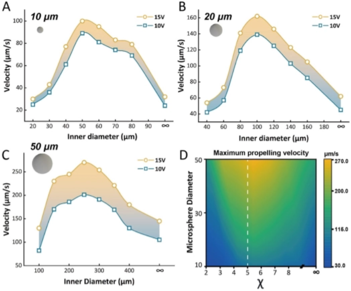
Figure 2. Microparticle Manipulation Results.
(A) Maximum propulsion velocity of 10 µm PS microparticles under light patterns of varying inner diameters.
(B) Maximum propulsion velocity of 20 µm PS microparticles under light patterns of varying inner diameters.
(C) Maximum propulsion velocity of 50 µm PS microparticles under light patterns of varying inner diameters.
(D) Relationship between maximum propulsion velocity and the curvature ratio χ for particles of different diameters.
In these experiments, semi‑circular light patterns with various inner diameters were used to drive PS particles of 10 µm, 20 µm, and 50 µm. Their peak velocities under each illumination condition were recorded. Complementary COMSOL Multiphysics simulations revealed how pattern curvature alters both the horizontal and vertical components of the dielectrophoretic (DEP) force.
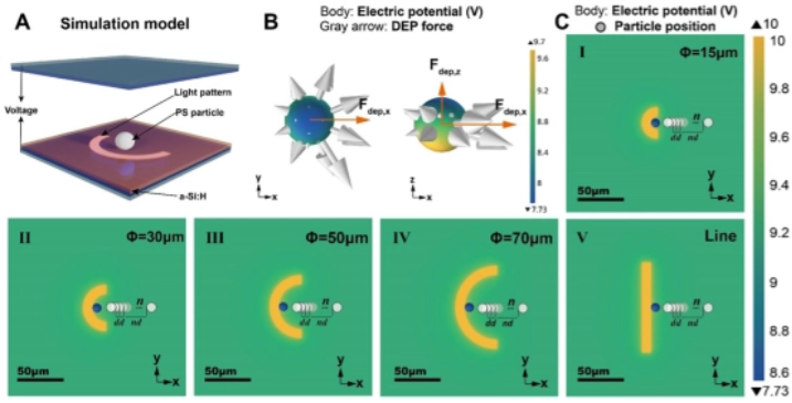
Figure 3. Simulated Potential Distribution and DEP Forces on PS Microparticles under Different Light‑Pattern Curvatures.
(A) Simulation model showing a PS particle and a semi‑circular light pattern.
(B) Electric potential distribution and DEP force vectors (gray arrows) acting on a PS microparticle positioned at the edge of a 50 µm inner‑diameter pattern.
(C) Electric potential maps around the particle when illuminated by light patterns of inner diameters 15 µm, 30 µm, 50 µm, 70 µm, and ∞. The particle’s location within each model is indicated.
V. Results
Results demonstrate that curvature significantly affects both horizontal and vertical DEP forces, shifting the particle’s equilibrium position and altering its peak speed. As the pattern’s curvature increases (i.e., inner diameter decreases), the maximum particle velocity first rises to a peak and then falls. An optimal curvature exists for each particle size: when the ratio χ (pattern inner diameter ÷ particle diameter) equals 5, particles experience the strongest horizontal and vertical DEP forces, achieving the highest transport speed and greatest motion stability.
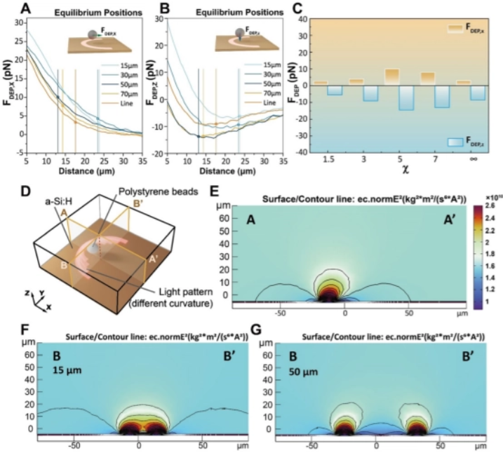
Figure 4. Analysis of DEP Forces and Electric‑Field‑Squared Distributions under Different Light‑Pattern Curvatures.
(A, B) DEP force components acting on a 10 µm PS particle in the x and z directions, plotted as functions of the distance between the particle and semi‑circular light patterns of inner diameters 15 µm, 30 µm, 50 µm, 70 µm, and ∞.
(C) DEP force at the equilibrium position for a 10 µm particle under various χ values, shown separately for x and z directions.
(D) Simulation model illustrating a PS particle driven by semi‑circular patterns of different inner diameters; lines A–A′ and B–B′ denote cross‑sections in the x/y plane.
(E) Electric‑field‑squared distribution along the A–A′ cross‑section; DEP force is proportional to the gradient of this field.
(F) Field‑squared distribution along B–B′ for a 15 µm pattern.
(G) Field‑squared distribution along B–B′ for a 50 µm pattern.
VI. Conclusions & Outlook
By uncovering the pivotal role of light‑pattern curvature in OET performance, this study opens new avenues for optimizing micromanipulation, microassembly, and microfabrication workflows. The collaboration between Prof. Shuailong Zhang, Prof. Na Liu, and OptoSeeker—powered by the OptoBot®500 Optoelectronic Tweezer System—demonstrates strong synergy between academic expertise and industrial R&D.
As this partnership deepens and OET technology matures, its application scope is expected to broaden, including more complex biomedical tasks such as precise manipulation of living cells. These advances promise to drive fresh breakthroughs in life‑science research and medical innovation.